
Keep the artwork movable
The research pointed toward masked projections for authoring and separate texture maps for delivery. A projection places an image using a controllable position, angle and scale. A mask defines where it may appear. This made it possible to adjust authentic sponsor artwork without repeatedly painting over it or changing the geometry to accommodate a graphic.
A useful precedent was Mihael Balać’s Honda S2000 breakdown, which used rendered views as artwork templates and a Blender control object called an Empty to position livery. The SF-26 workflow adapted that idea to its own curved panels and browser requirements. It did not adopt the article’s shader treatment as an export recipe.
Every mark needed more than a location. It needed the correct variant, proportions, side and receiving faces. Projecting onto a named body object alone was insufficient: that object could contain an interior surface or the opposite face of a thin fin. Depth, direction and explicit surface membership constrained the paint.
A recognizable logo can hide a reversal
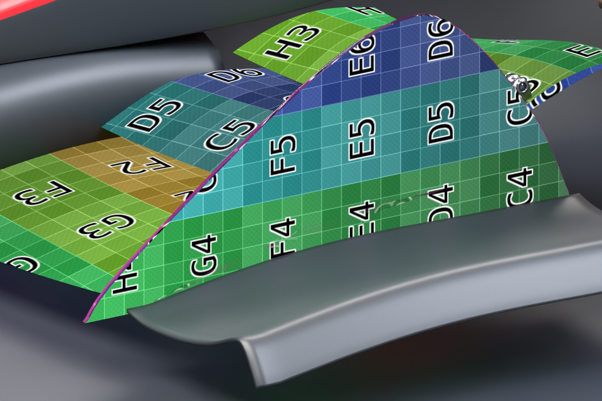
Shell’s nearly symmetric emblem looked plausible even when it could not prove the projection’s reading direction. Early pilot tests sent ordered charts through the artwork projectors to check handedness on both sides. The saved views below examine a different stage: destination UV mapping for baked textures on three different receiving surfaces.
UV coordinates describe how a flat image wraps onto a three-dimensional surface. Checker cells reveal where that wrapping stretches or compresses. They also expose seams that a broad red field can hide. Switch between the front-wing, engine-cover and rear-foil charts to inspect each receiver. These are separate diagnostics, not a matched before-and-after pair.
 Inspect image
 Viewing: Front wing · letter chart
Destination UV and bake-checker diagnostics. The views show different parts of the car; the diagnostic colors are not proposed livery.
Find the surface that actually receives the paint
A broken white border near the cockpit was initially easy to attribute to an overlapping mirror. A controlled view removed the occluders, then another assigned distinct colors to the receiving body parts. The discontinuity remained at the nose-to-sidepod transition. Keeping the camera fixed made the two images a useful explanation: the visible boundary crossed between different surfaces, and a matching formula alone did not make their painted edges meet.
Drag the divider on the image. Keyboard: arrow keys, Home or End.
The research behind the method.
These are the references recorded during the build. Reading about a method and proving it on this model were separate steps.
- Mihael Balać · Honda S2000 artist breakdown ↗
Artist-authored precedent for rendered artwork templates and controllable livery projection; not validation of this car.
- Blender manual · UV seams ↗
Background on arranging image coordinates across mesh surfaces and managing seams.
- Blender manual · Cycles baking ↗
Technical background for transferring material outputs into texture images.
- Blender manual · glTF export ↗
Portable material and texture conventions; actual delivery was checked independently.