
Look beyond the passing number
Blender builds a surface from connected vertices, edges and faces: a mesh. Tests can detect broken connections and unintended intersections. Those tests were valuable, but the project repeatedly exposed their limits. A cockpit surface could have the expected connectivity while folding over itself. A rear opening could meet its terminal width target while narrowing awkwardly immediately ahead of it.
The rear transition made that distinction tangible. Widening only the outlet created a flange with a neck behind it. The critic accepted the measured end width and rejected the integration. The correction broadened the surrounding sections progressively and removed an obsolete upper termination. Cross-sections then explained the improvement visible in the clay render; the measurement and image answered the same question.
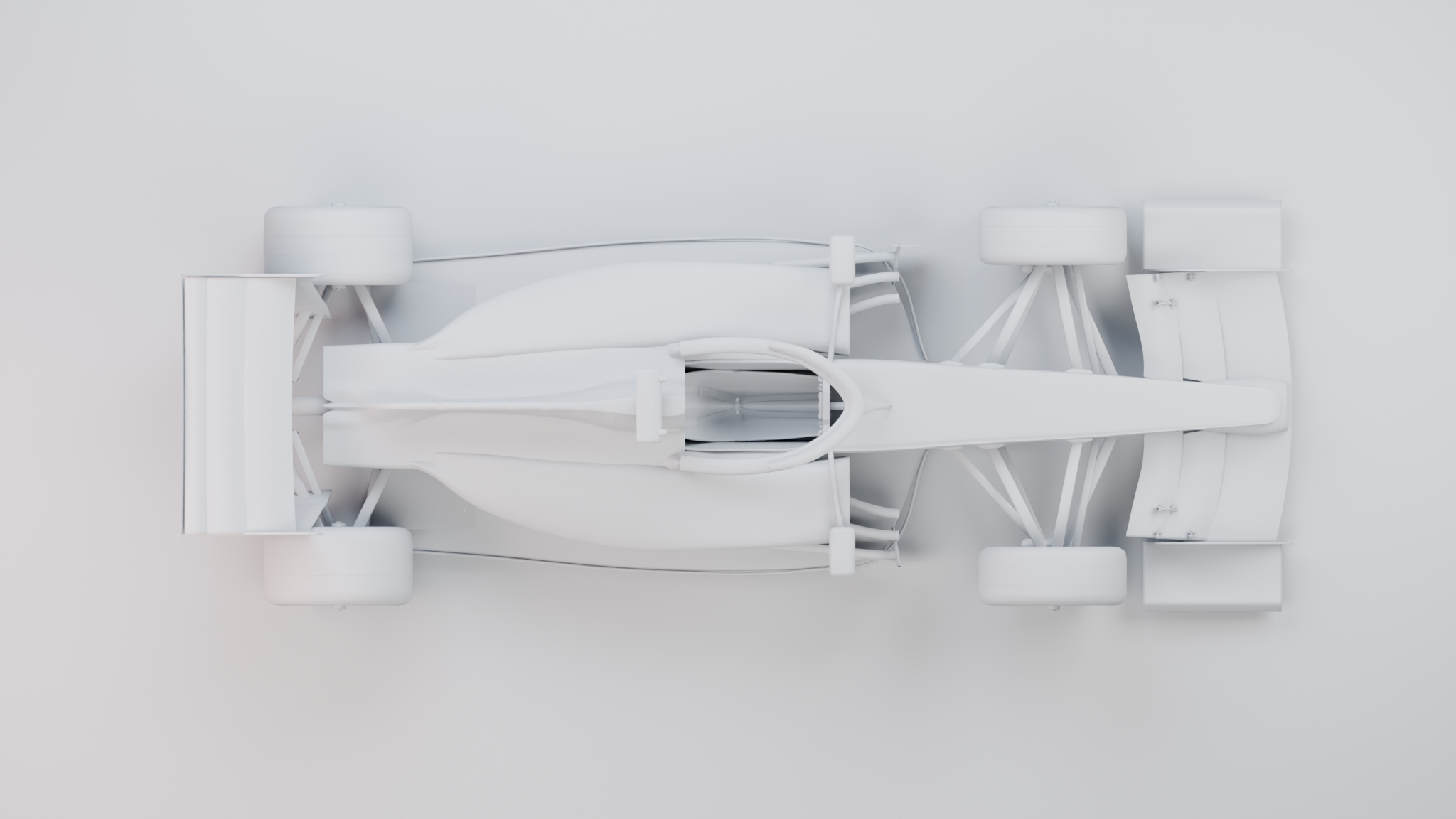 Inspect image
 Viewing: Top · orthographic
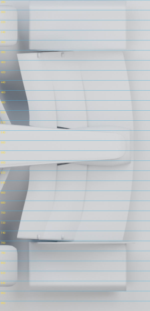
Geometry inspection views use neutral clay materials to make contour and attachment easier to read.
Read each source on its own terms
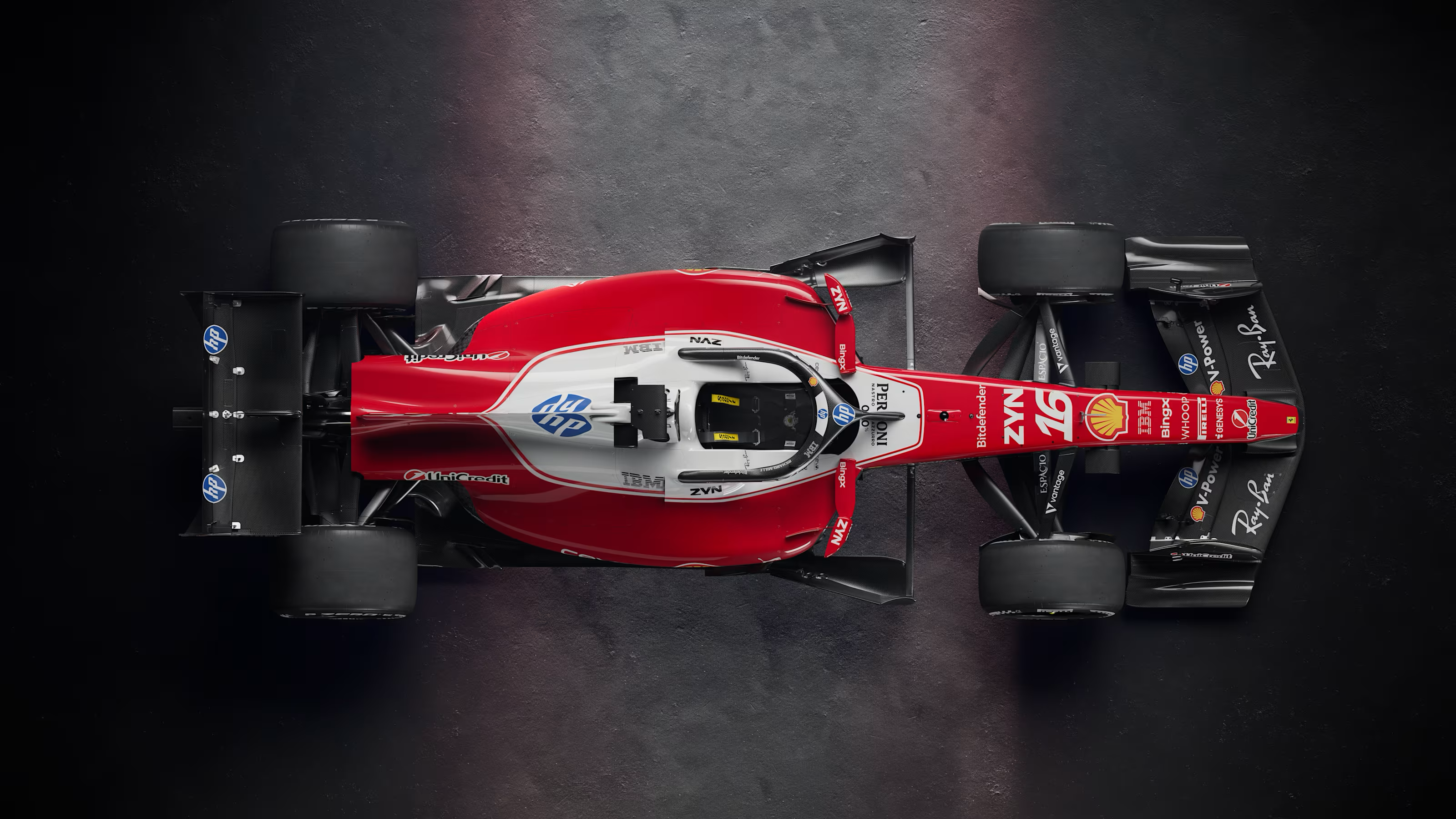
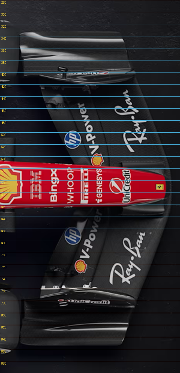
These external Ferrari images supplied complementary evidence. They are not a set of orthographic drawings or pixel-aligned counterparts to the clay views. Numbered guides on the front-wing crops record image coordinates for comparison, not manufacturer CAD dimensions.
 Inspect image
 Viewing: Overhead reference
External source images supplied for the project, distinct from our model renders.
 Inspect image
  Inspect image
 Bring the reference into the workspace
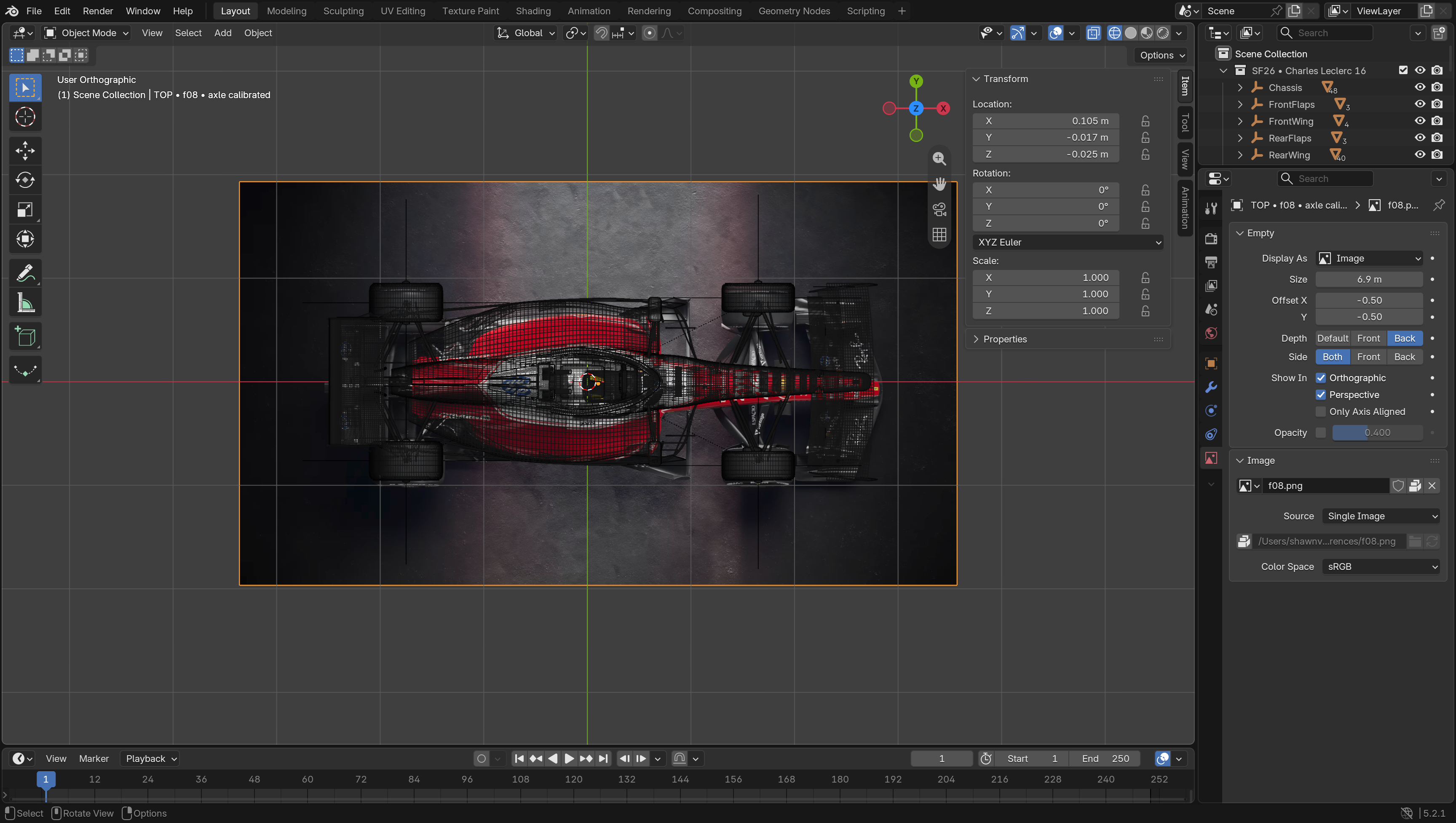
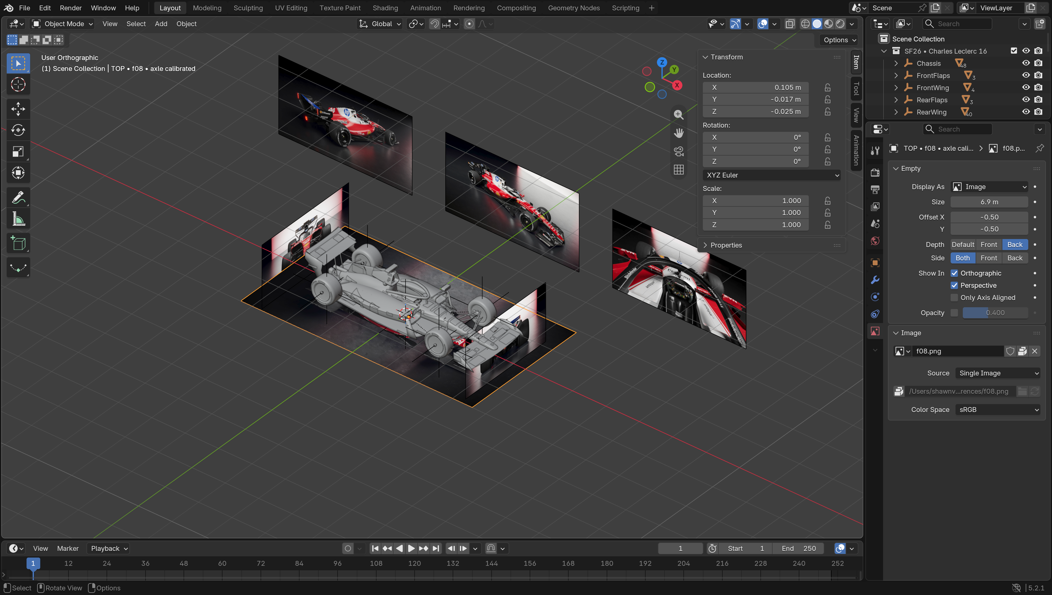
The saved Blender workbench places reference images around the model. In the overhead view, wireframe edges sit over the photograph while the interface exposes image size and position in metric units. Axle and tire landmarks supplied an estimated alignment; visible contour differences remain useful evidence of what still needed judgment.
These are current inspections of that saved workbench stage, not screenshots from the original modeling session or views of final delivery geometry. Its six image references include top, front, rear and detail views. This saved file contains no side-image objects.
 Inspect image
  Inspect image
 Repair the attachment, then inspect it again
The sidepod inlet had a doubled edge and an apparent hanging ridge. Its outer opening and separate inner duct were individually modeled, but their contours had different vertex counts and no connecting rim faces. A thin lip laid around the opening disguised neither the gap nor the missing attachment.
The repair used the actual outer perimeter to build a connected rolled rim and recessed throat while preserving the opening’s bounds. A remaining bar proved to be the mirror support crossing below the inlet roof. Rerouting that support above the rim removed the obstruction without moving the mirror housing. The final evidence belongs to the 21:45 checkpoint; an earlier 21:34 version still preceded the support refinement.
Drag the divider on the image. Keyboard: arrow keys, Home or End.
Sampling changes the surface
The halo landing offered a different failure. A smooth mathematical deformation still produced large triangular facets because the existing mesh sampled it too coarsely. More local section samples allowed the surface to follow the intended transition. The accepted candidate retained the cockpit opening and nearby controls. Its local contour improved; the exact Ferrari ledge width remained an estimate.
Drag the divider on the image. Keyboard: arrow keys, Home or End.